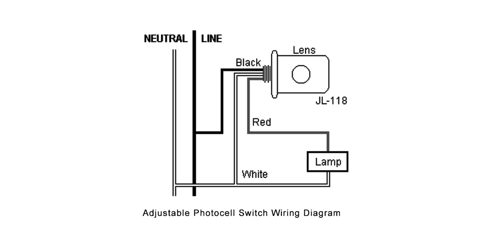
photo eye wiring diagram
Remove power on main control board for 2nd pair of photo eyes. Locate the power wires for the switch installation.
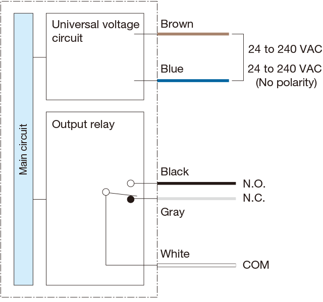
Photoelectric Sensors Amplifier Built In Type Universal Voltage Sensors V2 Series Circuit Diagram Dimensions Optex Fa Global
0 out of 0 found this.
. Box Detector Sequenced Operators Wiring Diagram. Baldor Motor Electrical Connection Wiring Diagram. There will be two.
The 4 pin M12 plug standard is broken down as follows. Specification Sheet Wiring Diagram Installation Manual. A photo eye primarily consists of an emitter - to emit light and a receiver to receive the emitted light.
99 Liftmaster Chamberlain 41A5034 photo eye. Place the dip switches in the. Go to the location where you are wiring the photoelectric switch.
PAIR 2 PHOTO EYES. Ad Enjoy low prices on earths biggest selection of books electronics home apparel more. For example if a module will be powered up.
Garage Door Photo Eye Wiring Diagram. One black hot and one white neutral. For example if a module.
BLACK WIRE IS 120 VOLTS SO TURN OFF SWITCH OR CIRCUIT BREAKER. The AC 12hp motors have 3 wires 1 red 1 blue and 1 white wire that are not connected to either the high or the low voltage wire harness. Step 1 - Photo Eye Wiring Scheme.
The photocell to control your 1000 watt outdoor light fixture needs 240 volts to operate the photo cell and because the 240 volt circuit does not have a neutral you cannot use a 120 volt. 33 Photocell Wiring Diagram Pdf - Wiring Diagram Database Wiring Diagram Led Eye - Wiring Diagram Schemas and also. The 4 pin m12 plug standard is broken down as follows.
PAIRING YOUR 2ND PHOTO EYES. Connect sensors black wire to black wire. Box Detector Free Exit 24VAC Wiring Diagram.
Photo-eye Thru Beam 24VDC Reflective Wiring Diagram March 23 2020 2021. Here is my wiring diagram third photo and instructions. Monitored Photo Eye for Linear Apex II Control Board Meets UL325 6th Edition Effective Date Jan 12th 2016 Works on all Linear.
18 Pics about Kwans research interests. By monitoring the electrical output of the receiver a control system. Effectively read a electrical wiring diagram one has to know how the components in the system operate.
Photo Eye 24VDC Thru Beam. The standard in industrial automation is to run a 4 wire M12 connector to field devices.

Can Bus Wiring Diagram A Basics Tutorial Tek Eye
Primitive Angel Eye Wiring Diagram Bimmerfest Bmw Forum
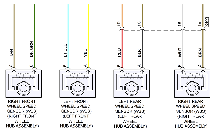
Wheel Speed Sensor Diagnostics
Wiring Diagram For Color Sensor One Token Slot Download Scientific Diagram
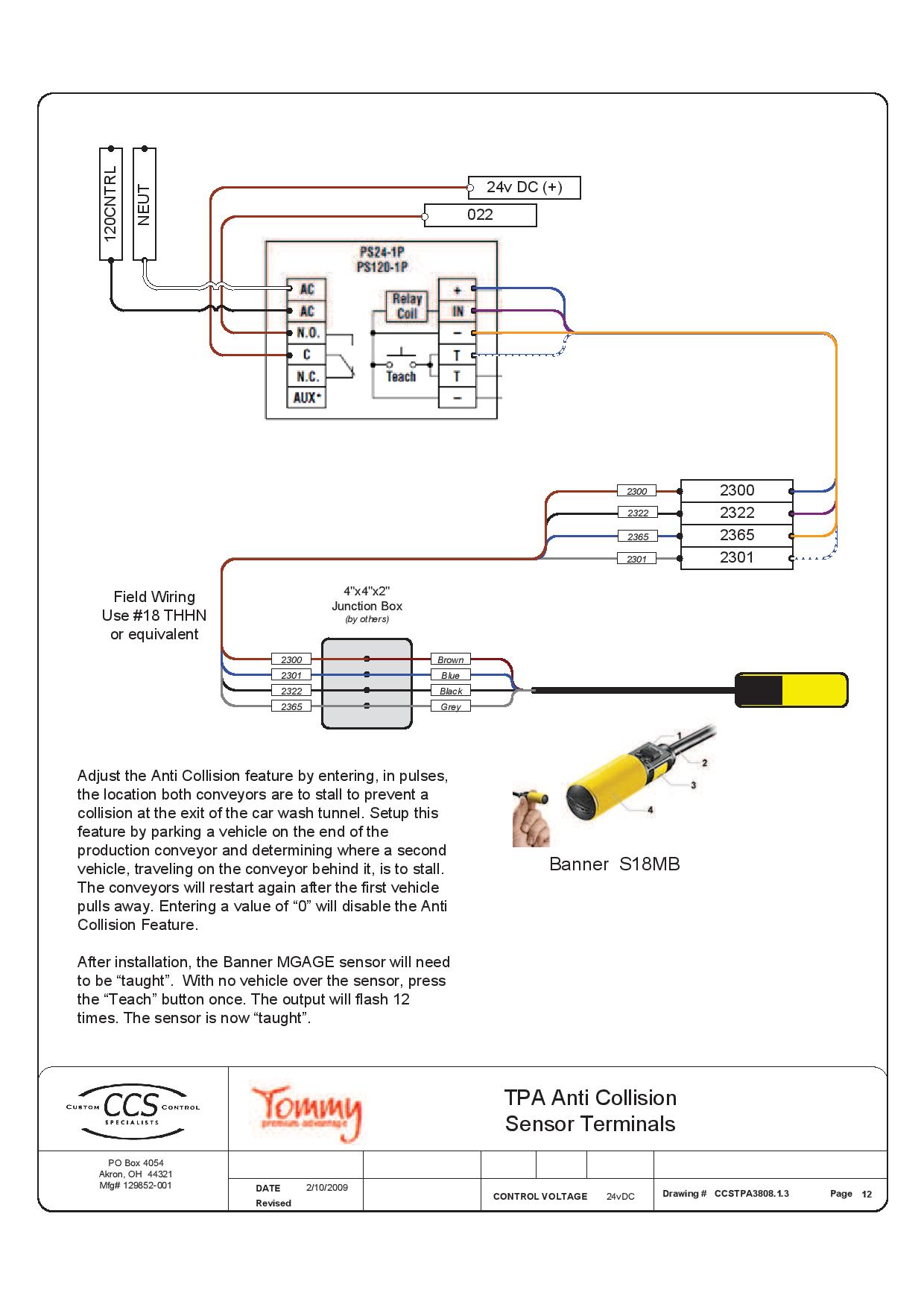
Wiring Anti Collision Tommy Car Wash Systems

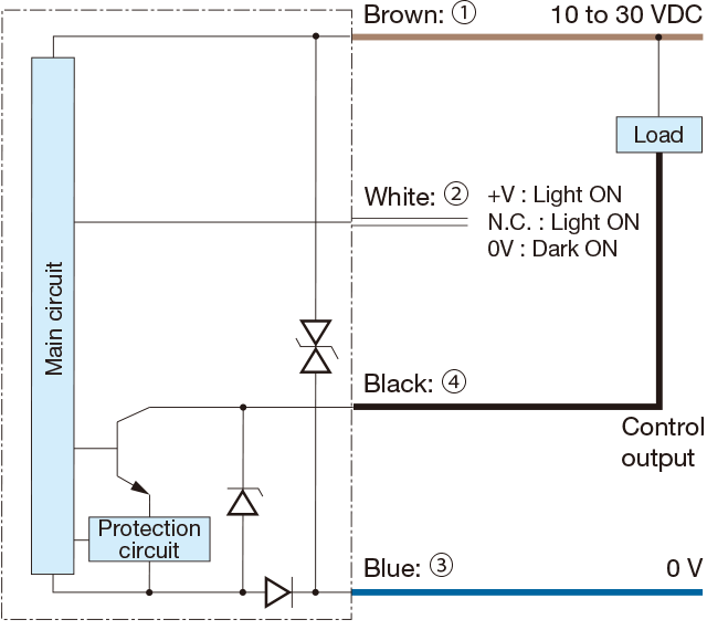
Photoelectric Sensors Amplifier Built In Type Universal Voltage Sensors V2 Series Circuit Diagram Dimensions Optex Fa Global

Cylindrical Inductive Proximity Sensor Gx U Gx Fu Gx N Discontinued Products I O Circuit And Wiring Diagrams Panasonic
Electrical Wiring Diagram Sensor Load Current Sensor And Stator Download Scientific Diagram

Instromet 0 10v Dc Wind Speed Sensor Wiring Diagram Instromet Weather Systems Ltd Pdf Catalogs Documentation Boating Brochures

Motion Sensor Wiring Diagram Motion Sensor Wiring Diagram Motion Sensor Youtube

Photocell Sensor Wiring Diagram Instruction

How To Wire A Photocell Switch To Lighting Loads With A Contactor Learning Electrical Engineering
Back To The Basics How Do I Wire My 3 Wire Sensors Automation Insights

Photoelectric Sensor Wiring And Setup Youtube

Photocell Sensor Wiring Practical Video Youtube